
The scope of this teardown is to provide a step by step disassembly guide in order to uncover all components.
We believe that hardware-wise the MiR family in general is a really interesting platform.
Since most of its parts are made by third parties, it's easy and understand what each part does and why is there,
therefore maning this robot very friendly to be serviced and repaired on the eventuality that some component gives up the ghost.
Although this might just be a happy unforseen consequence seeing that some parts are held by screws,
and some others, (thankfully, the minority) are riveted.
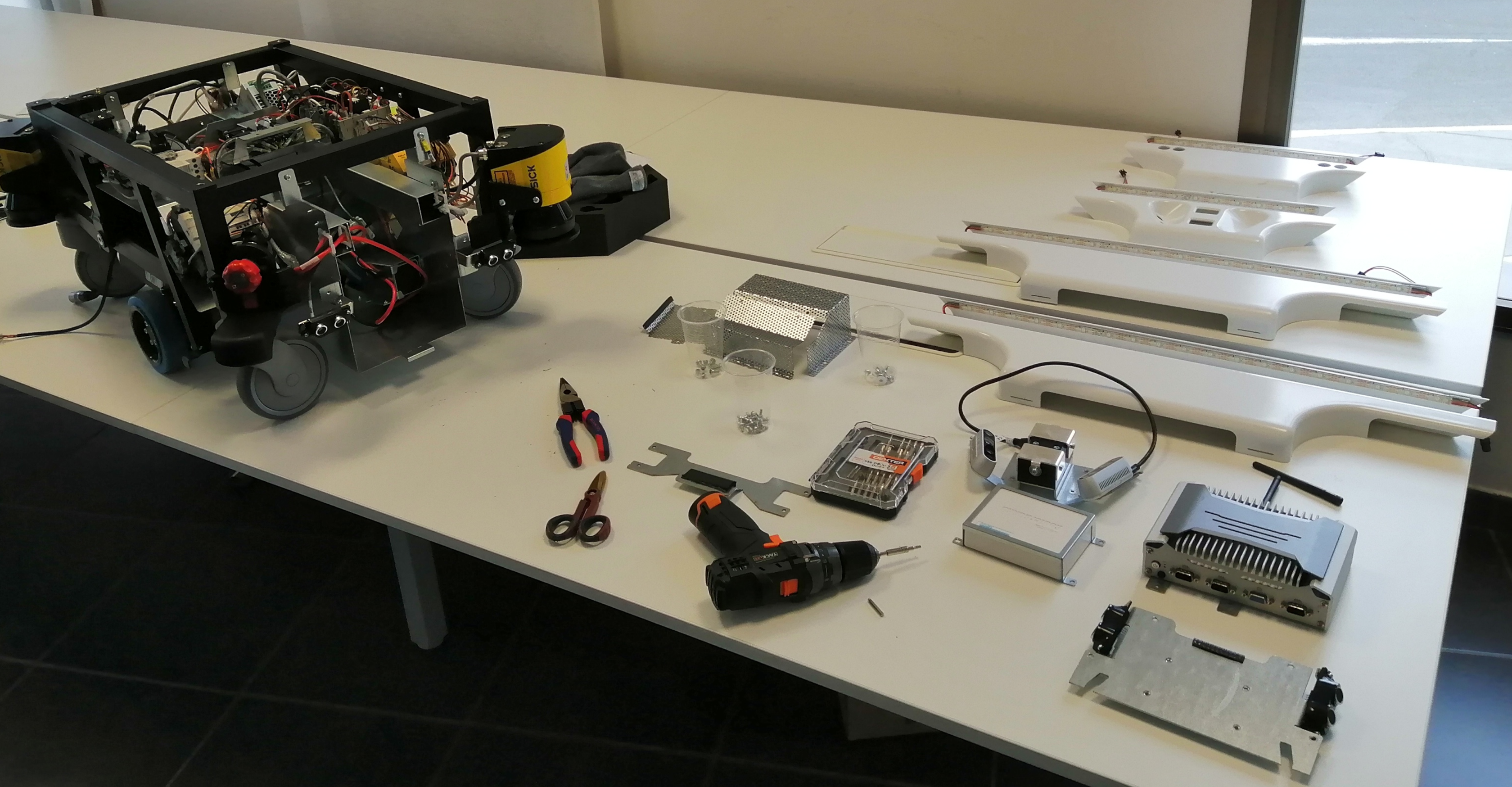
If you have your tools ready, let us begin.
The top shell just sits on top of a metal frame in order to protect the electronics inside.
Lift it up.
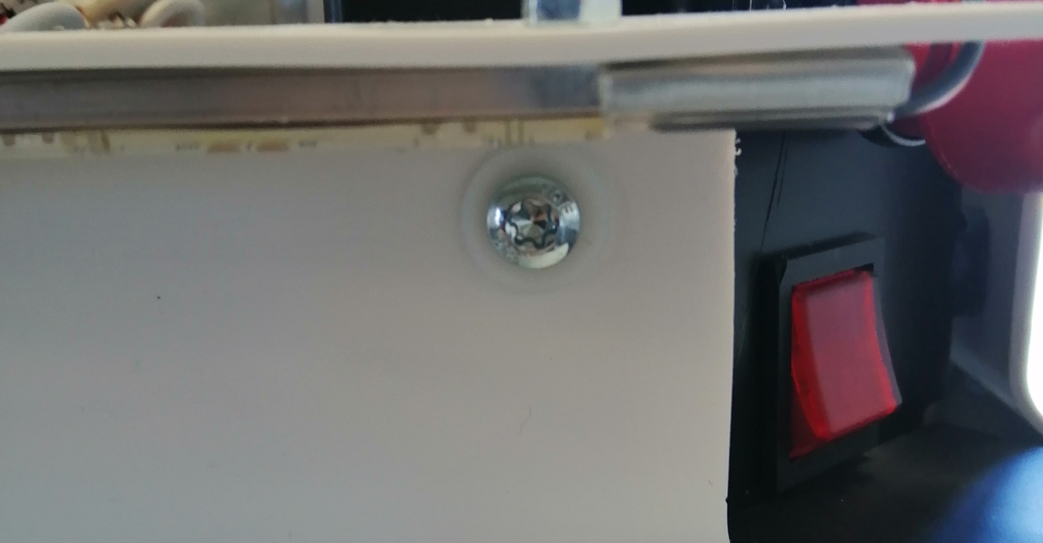
To prevent any potential movements you should dissconnect the main power line by
flipping down the circuit breaker switch
When we opened our MiR for the first time we were kind of surprised, compared with other robotic platforms (stay tuned 😈) revealed a lot of third party components with next to no propietary hardware from Teradyne itself.
Disconnect the LED molex connectors located on the corners

There are 4 connection points. Each one located a corner. They are daisy-chained together.
There is two screws per fender, each with a poliamide washer use a T20 bit.
Mind that they are latched by a metal lip below, so tilt the top slightly towards you and slide it downwards to get them out.
The retaining plate is held in place by 4 torx screws located in the corners by the ultrasound sensors.
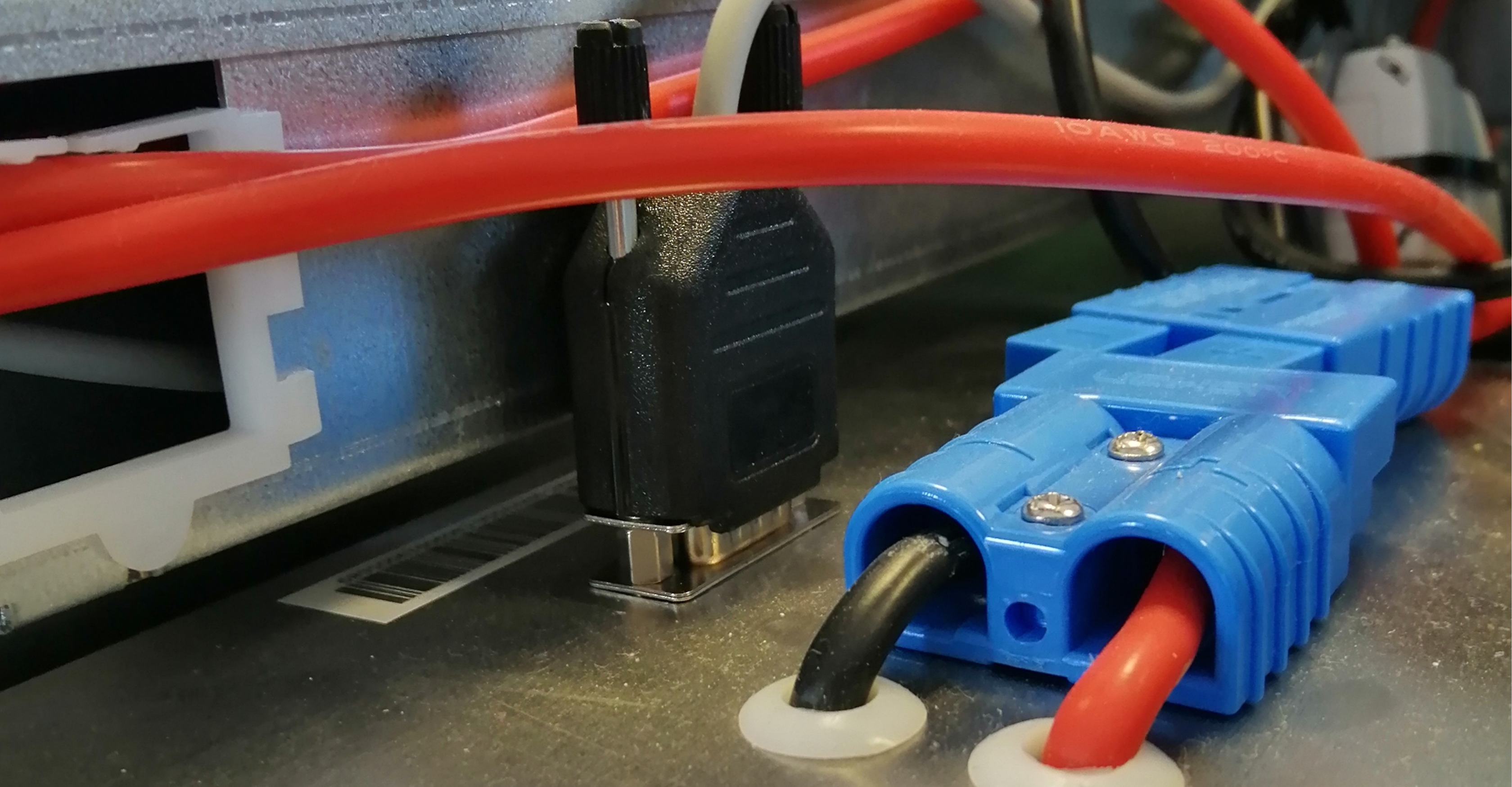
Remove the power connector and the sensor data line from the battery. Then remove the battery with caution.
Remove the cage covering the teensy and the LED Controller board by unscrewing two torx screws.
The two screws closer to the speaker release the speaker holder. It is advised to hold the speaker when unscrewing in order to prevent an accident.
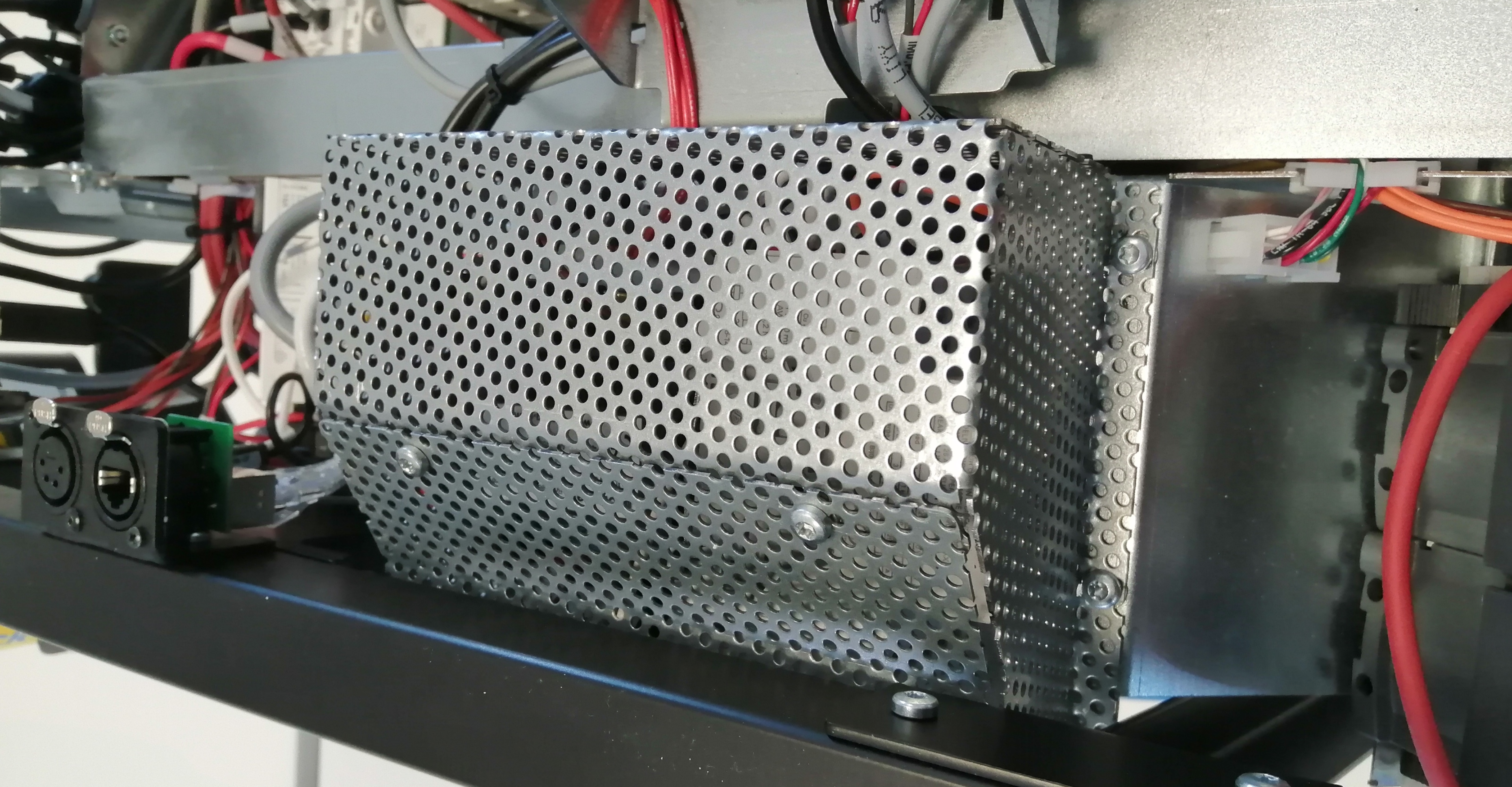
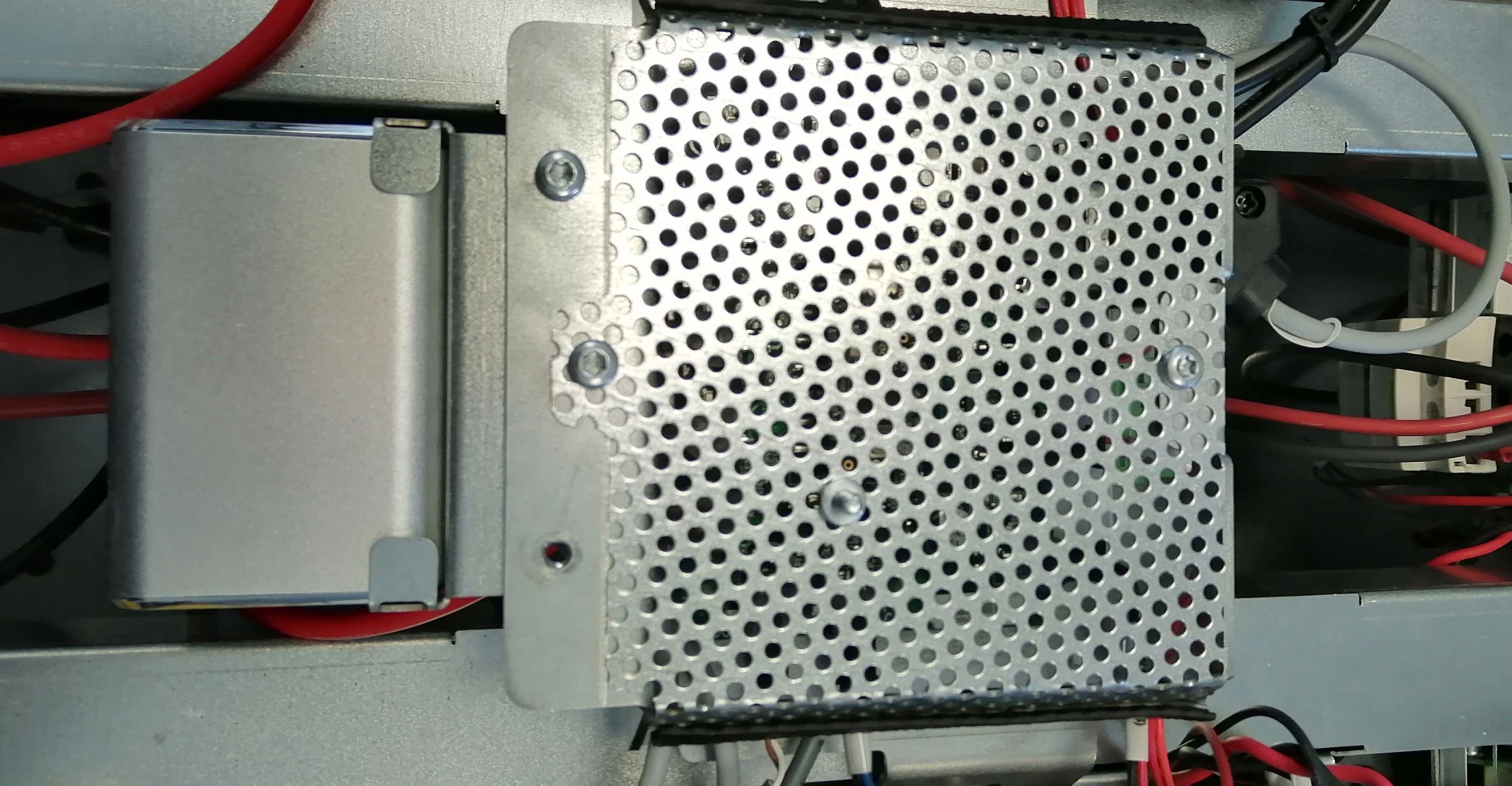
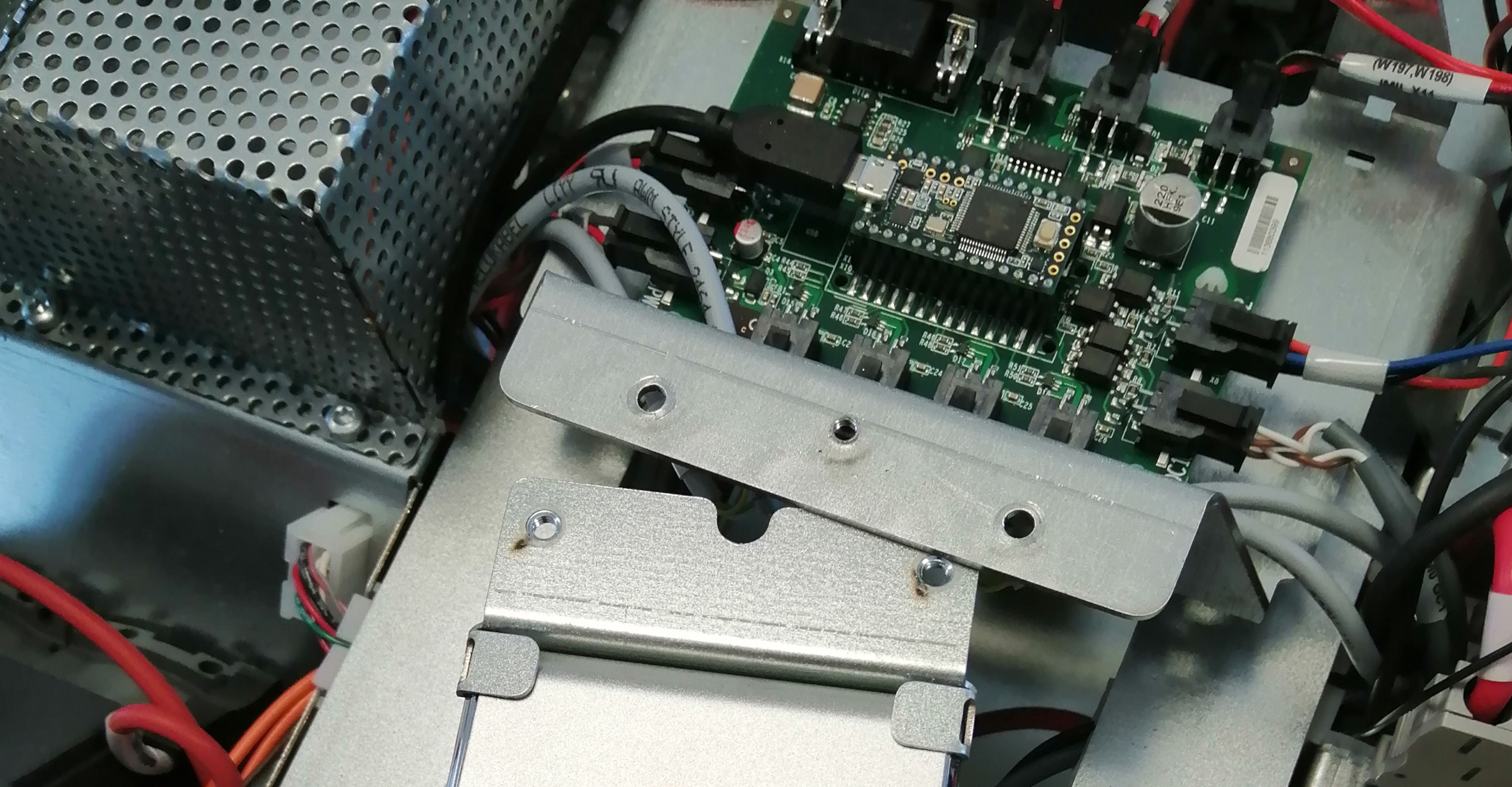
Remove the 6 screws holding the cage that covers the motor controller.
Start by unscrewing the two screws located on the sloped panel and slide it out. Then the other 4.
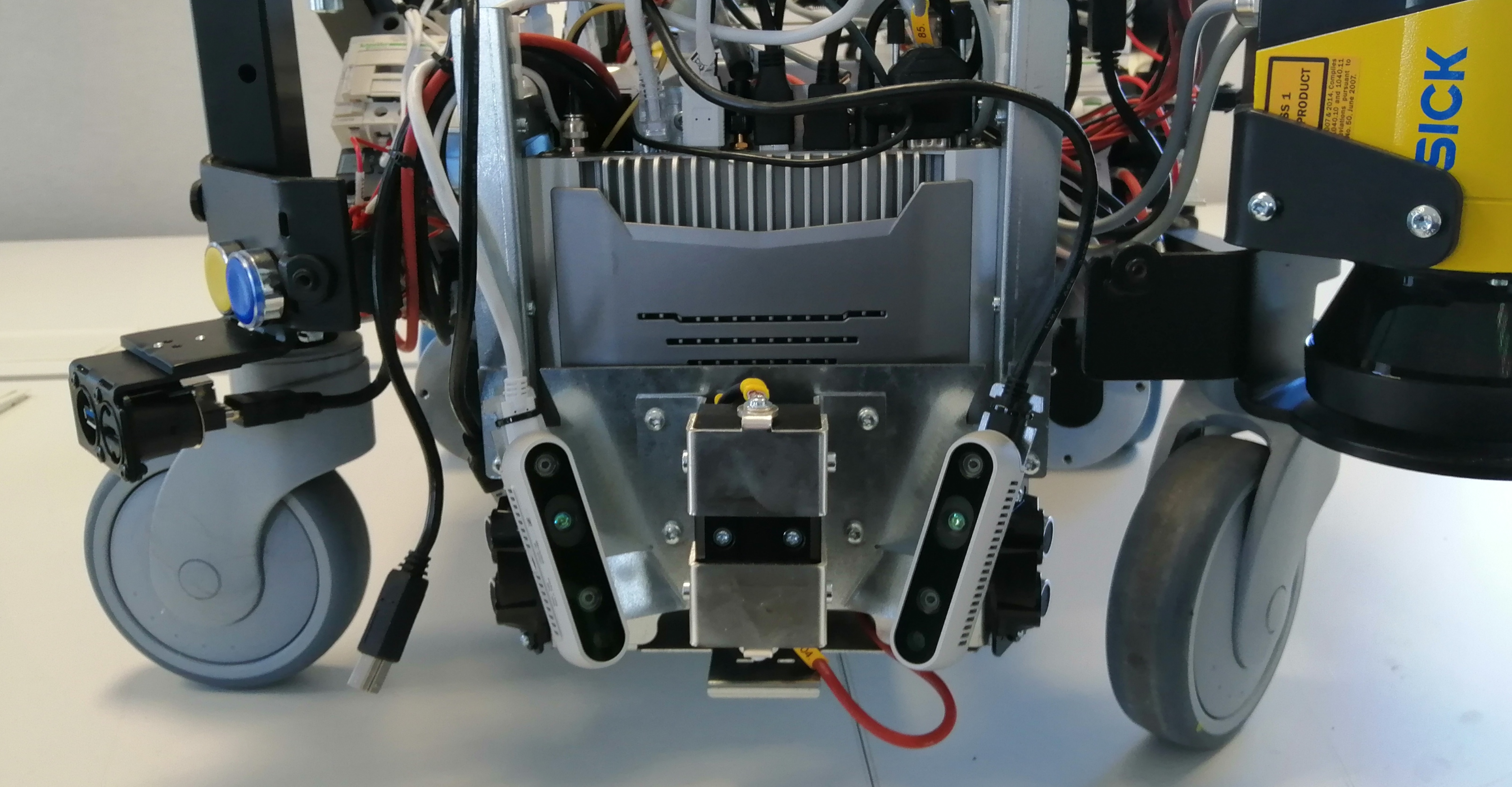
Unscrew the 4 torx screws that hold the charging pads and the SLAM cameras.
Remove the terminals from the charging pads. Take note of the polarity before disconnecting. Remove the USB wires from the SLAM cameras.
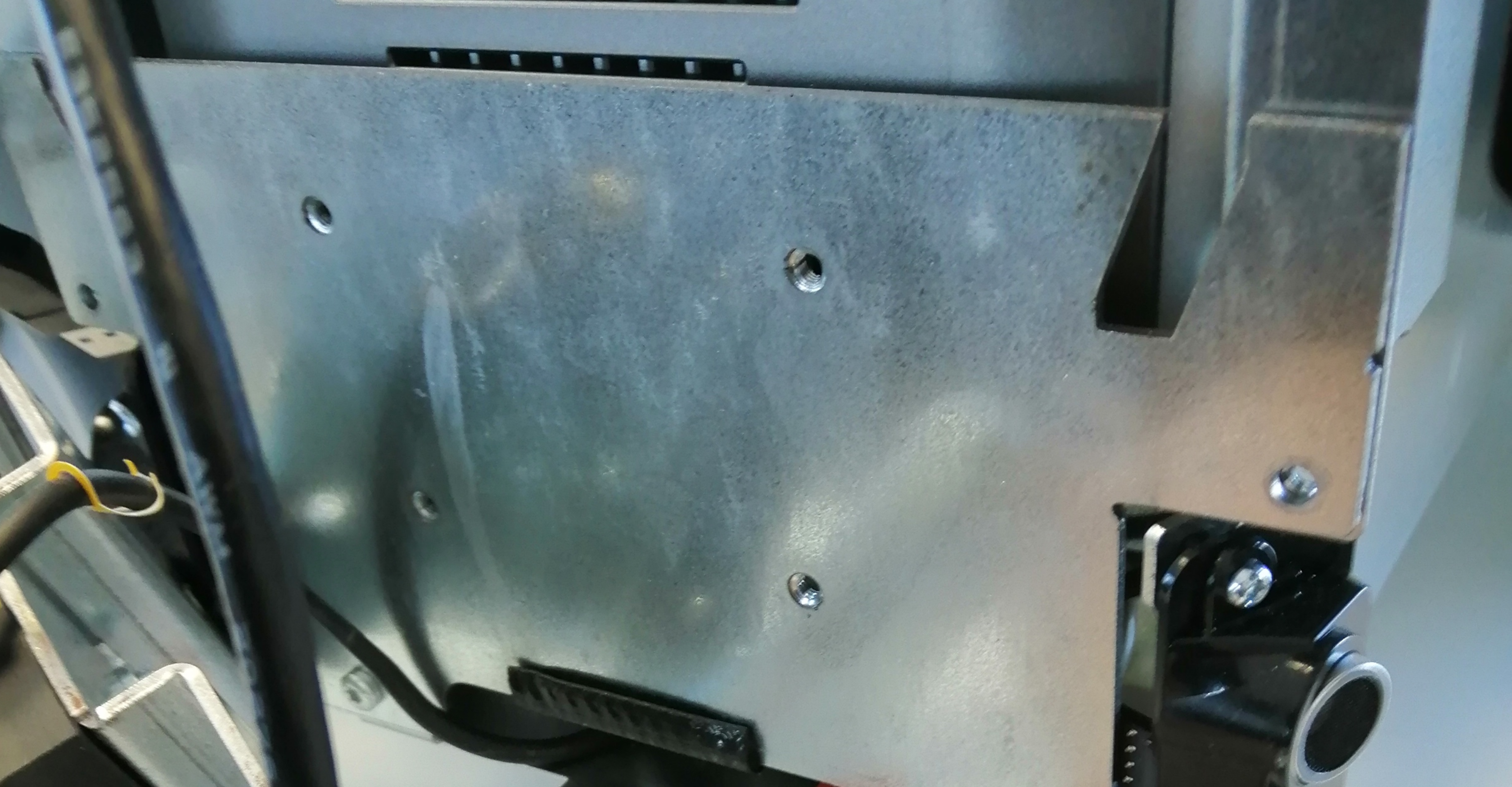
Remove the front plate protecting the PC by unscrewing 4 crews on the side.
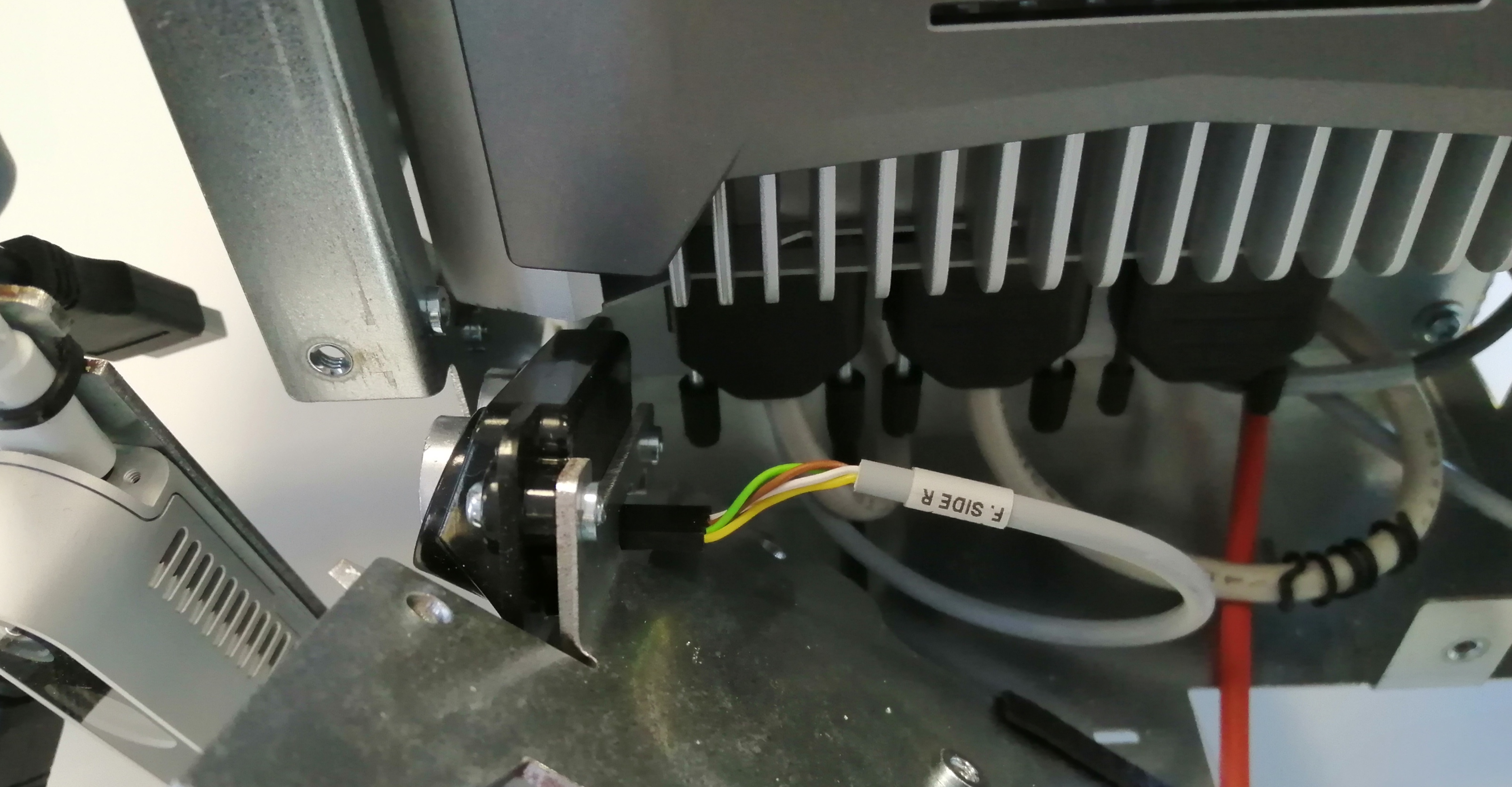
Then disconnect the Ultrasound sensors.
Proceed to disconnect all the connectors with care.
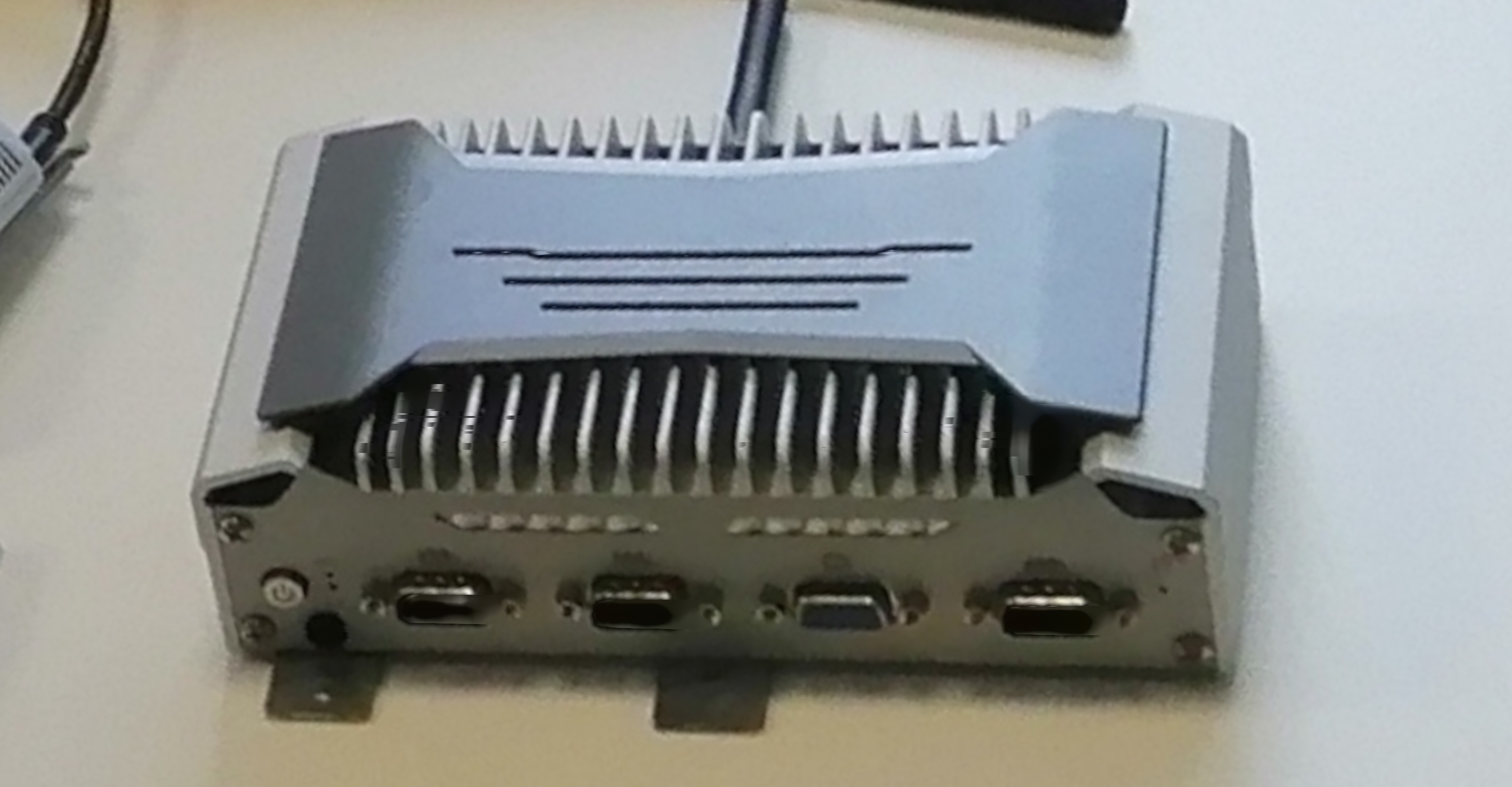
Lastly remove the two screws on the top and release the NUC.
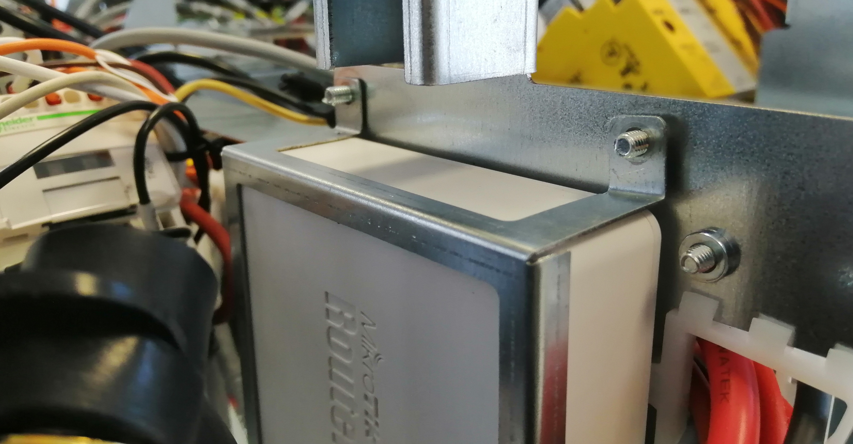
Using a 7mm socket wrench, remove the 4 autolock nuts.
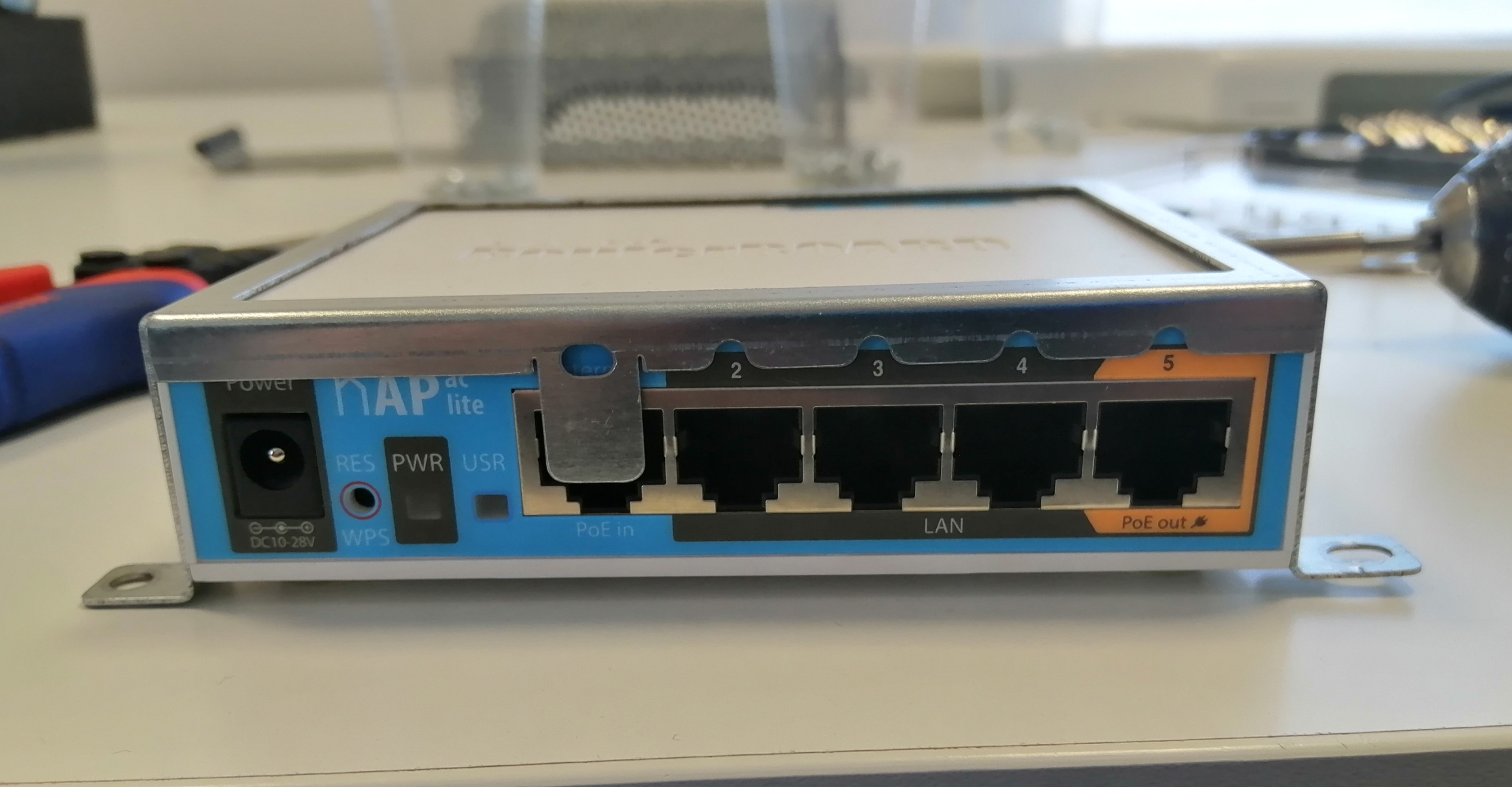
Disconnect the power and ethernet wires, then take out the router.
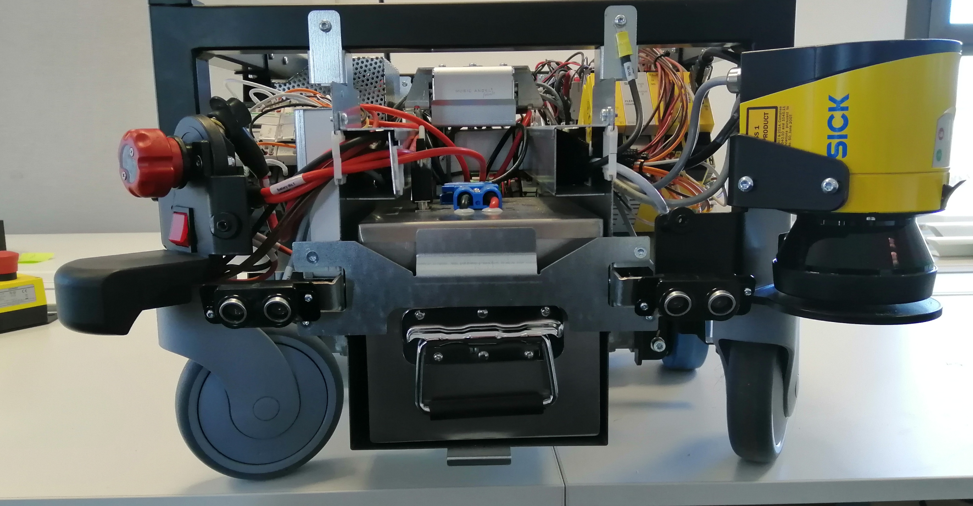
With this part concluded, we can go ahead and list all the components inside the body.
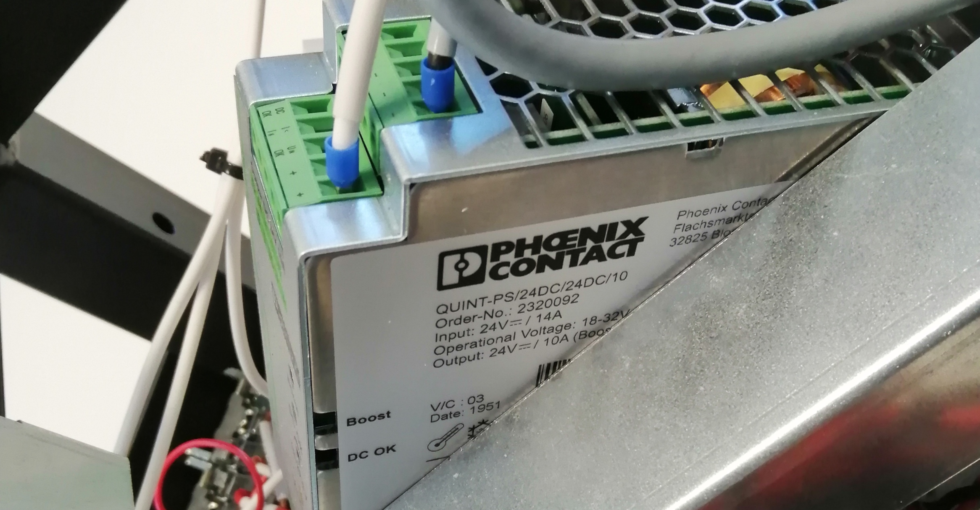
24V Power Supply
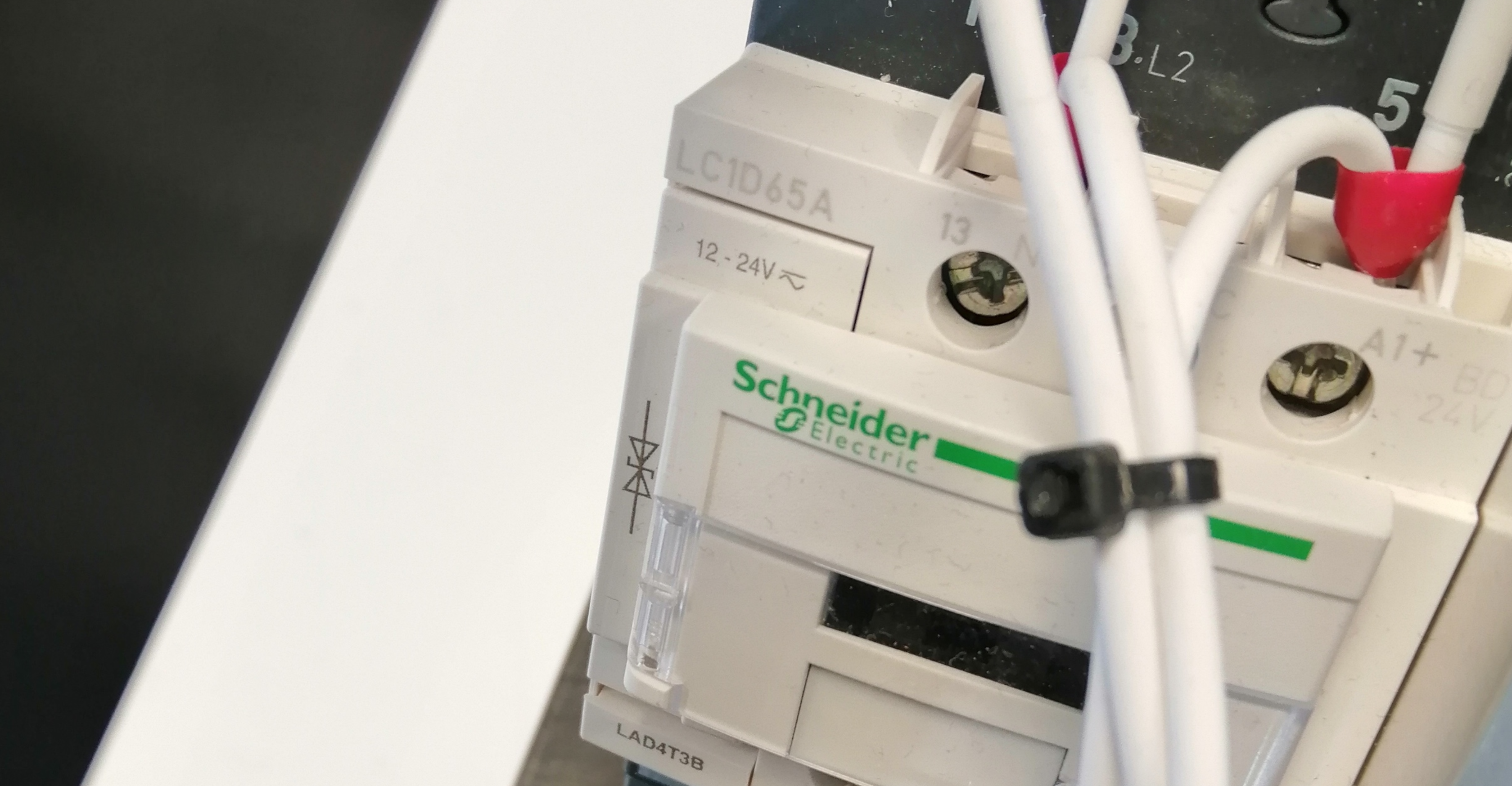
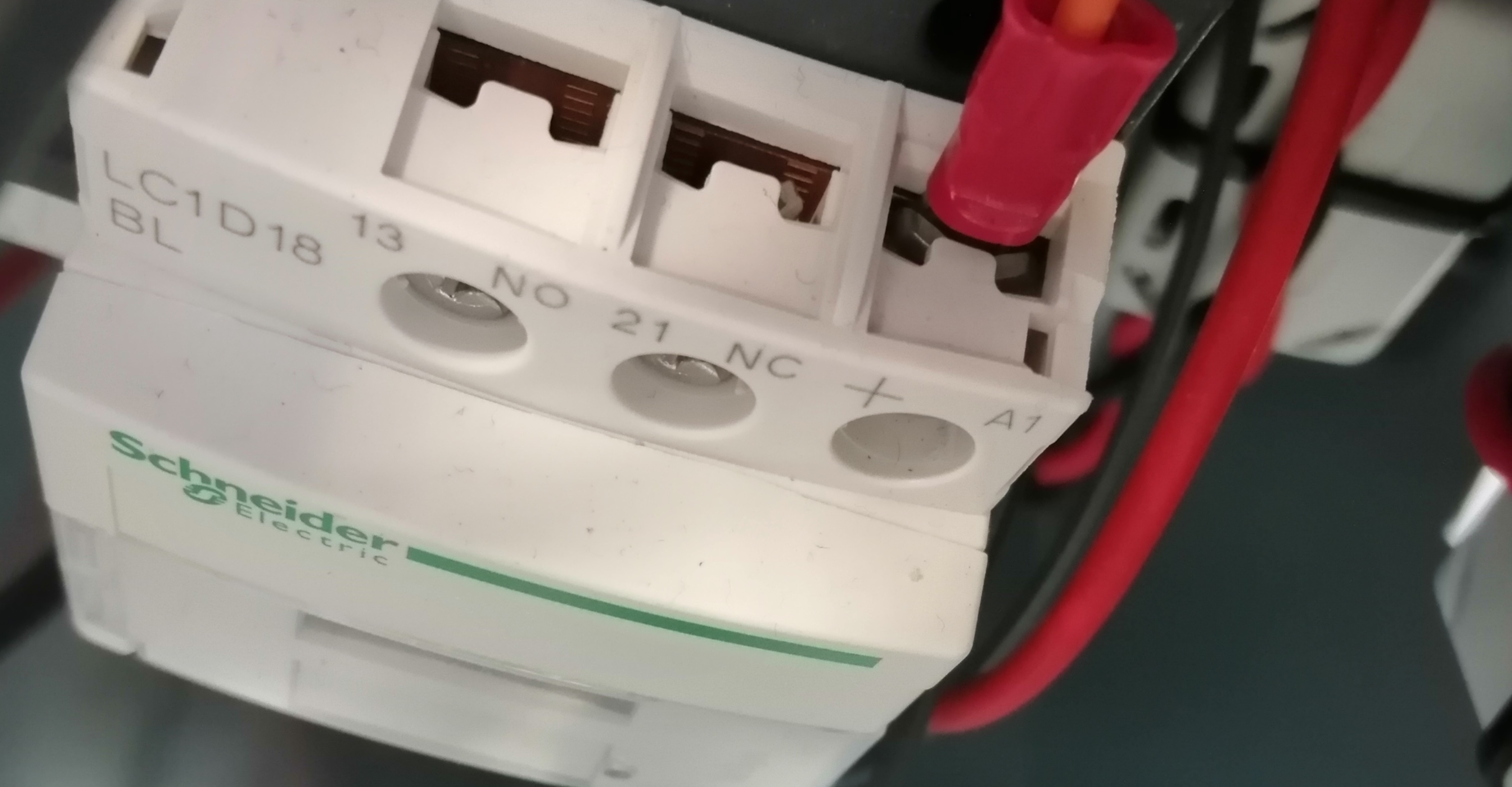
Low voltage D-line contactors
Motor control resistive load contactor
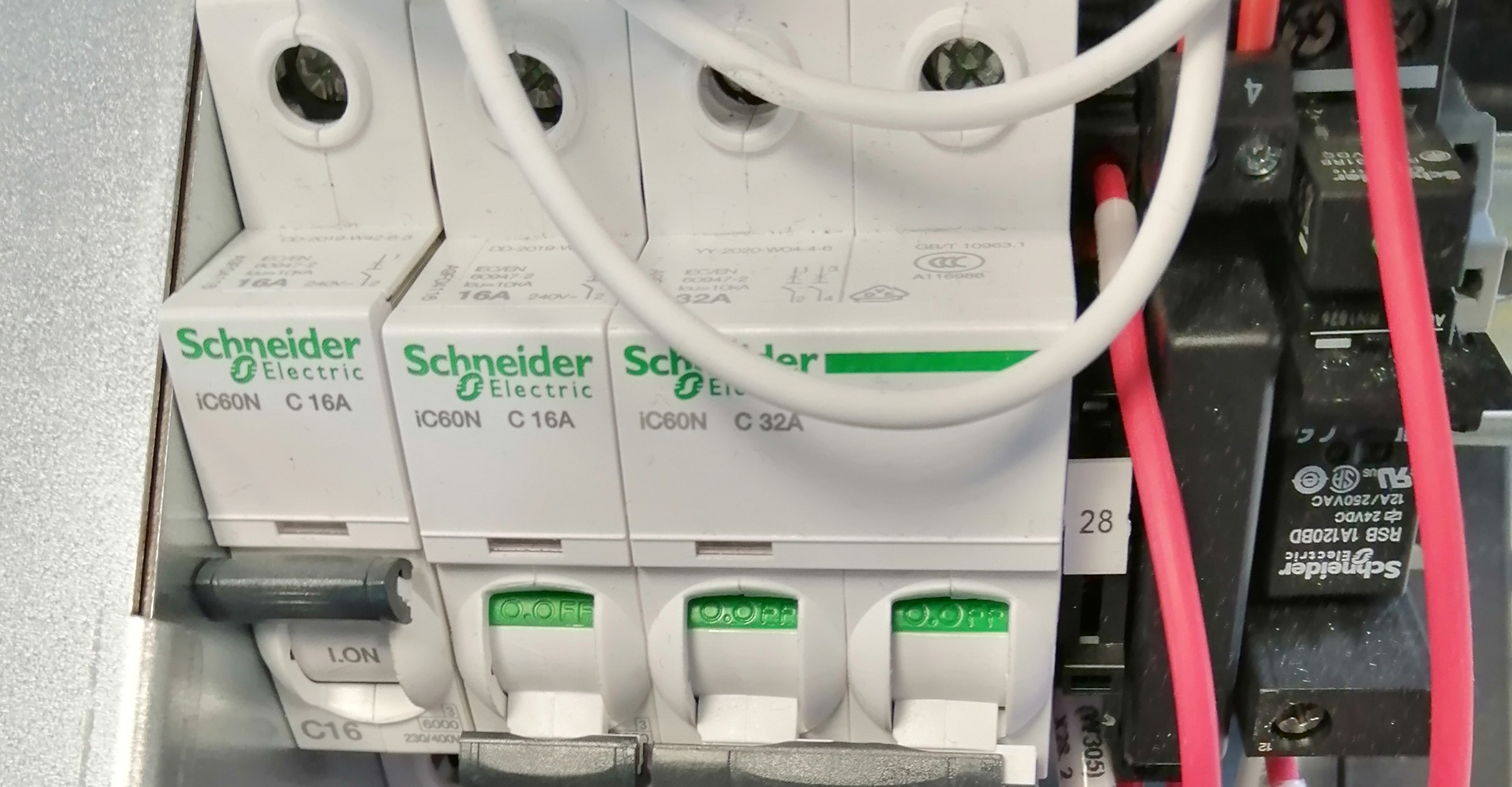
Circuit breaker
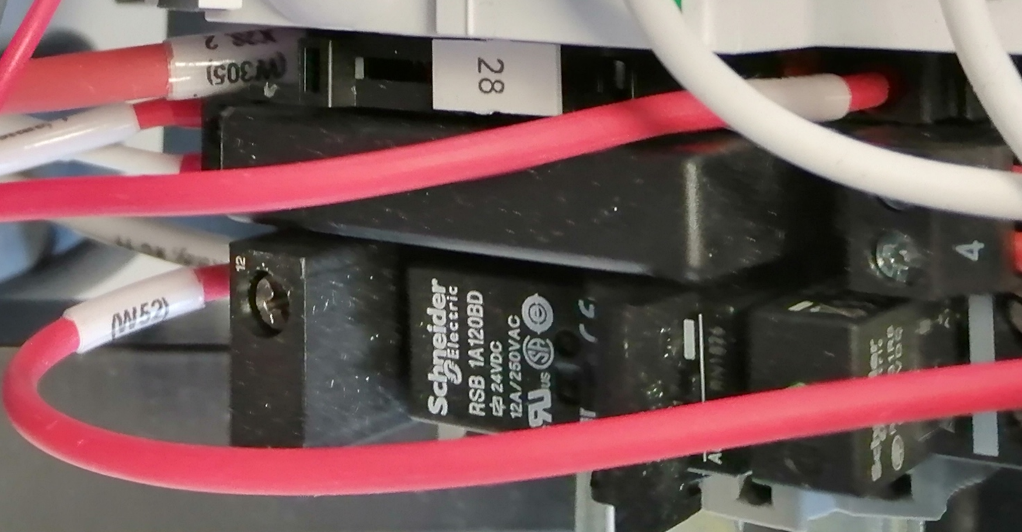
General purpose relay
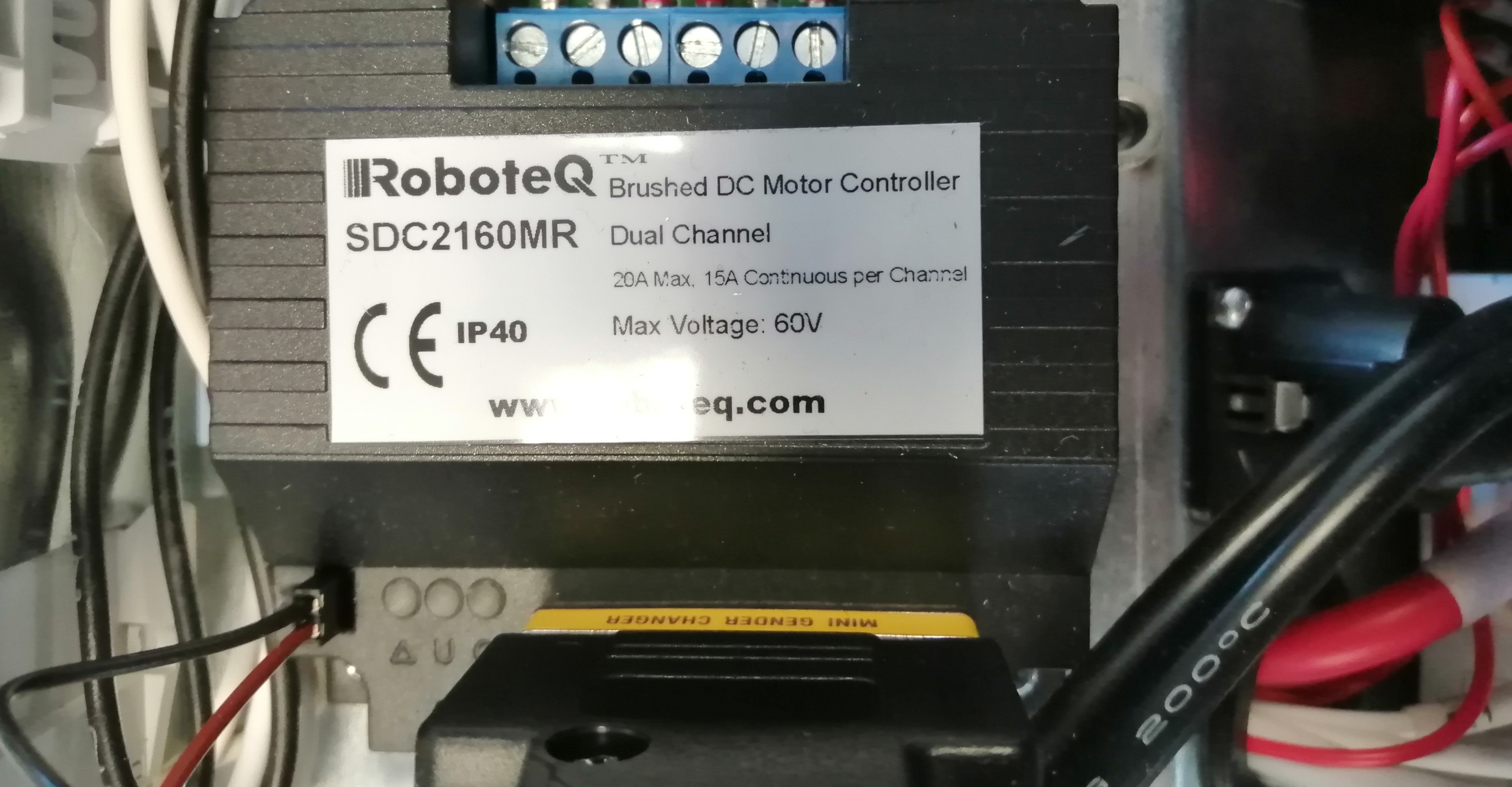
DC motor controller
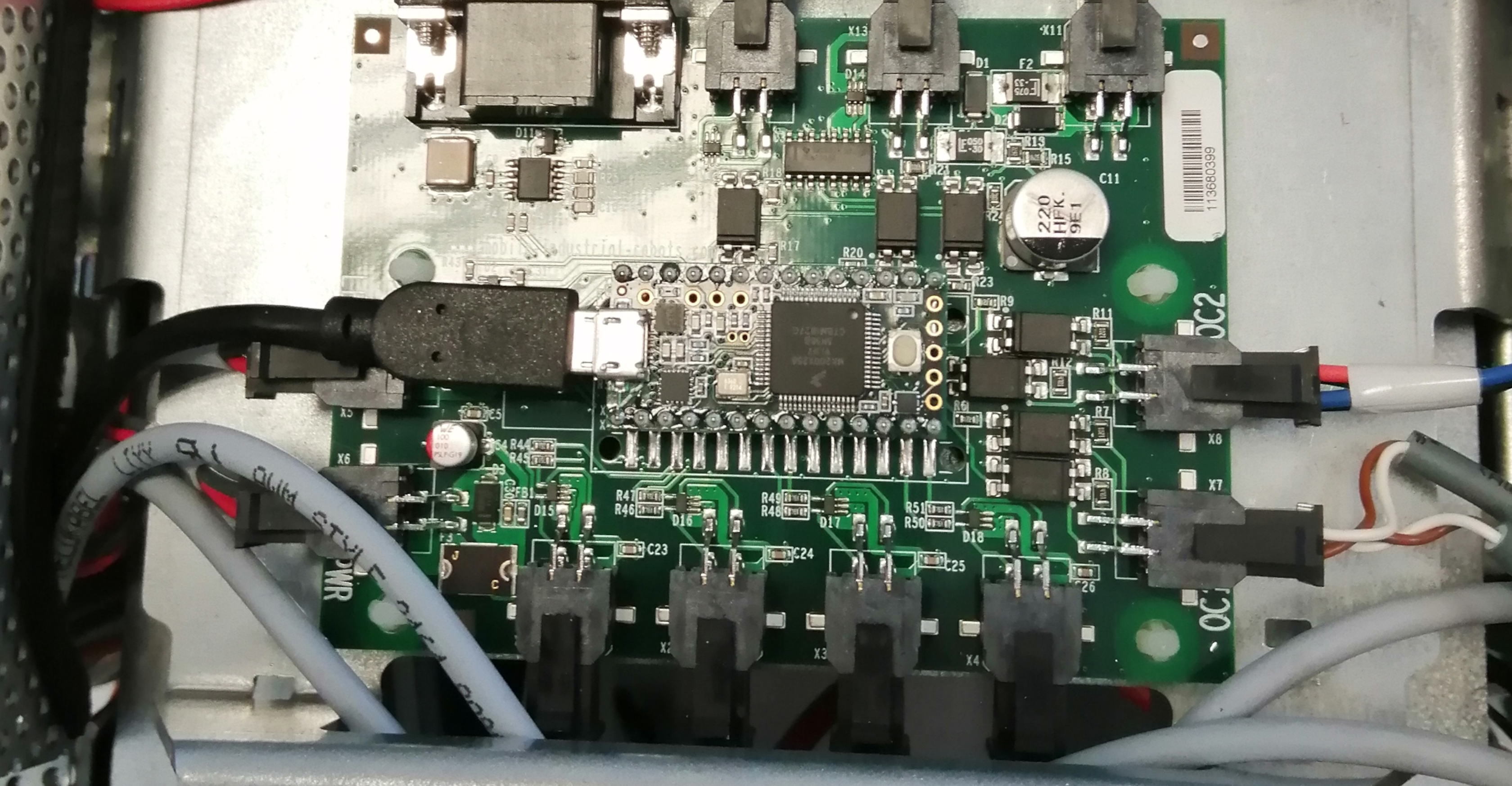
Teensy 3.2 plus LED controller carrier board
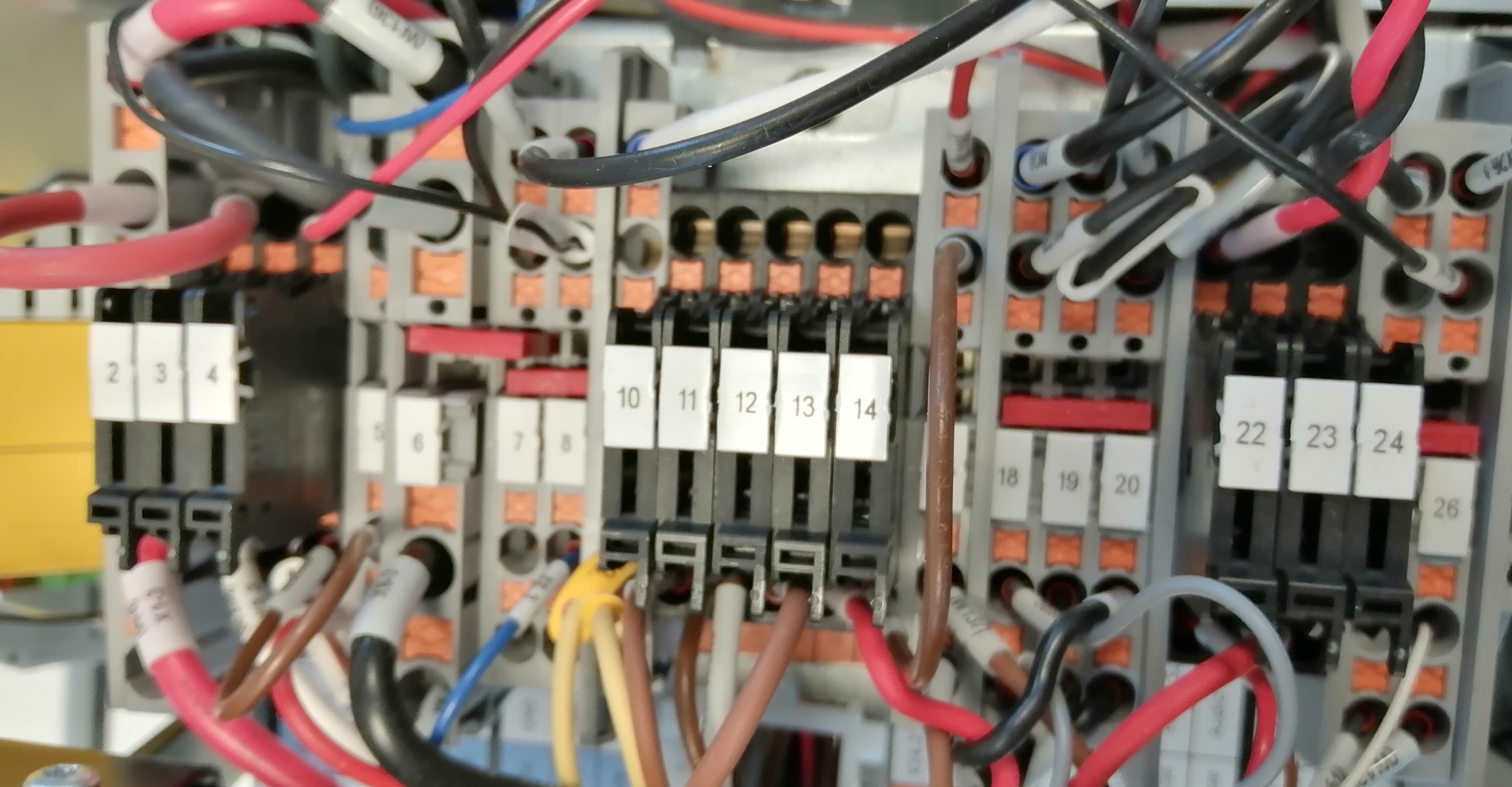
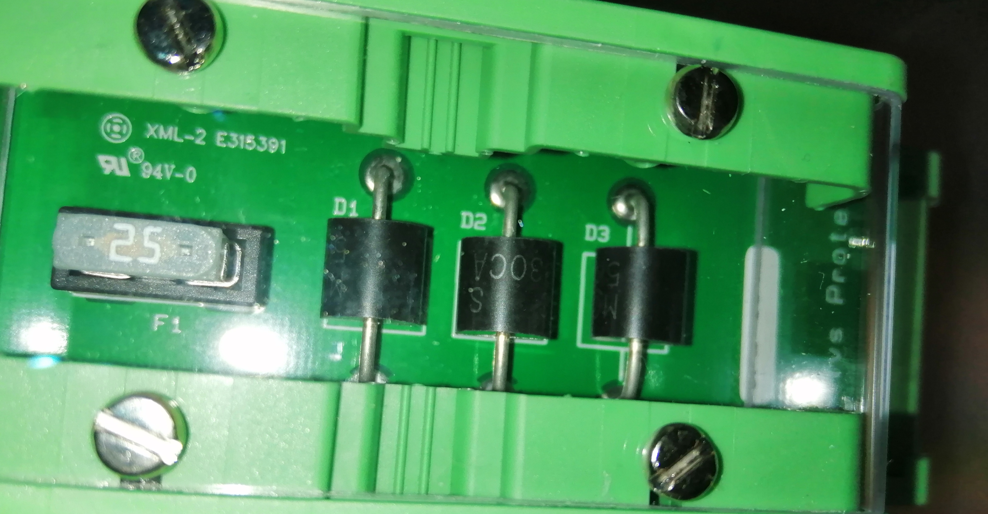
Board containing fuses of different values.
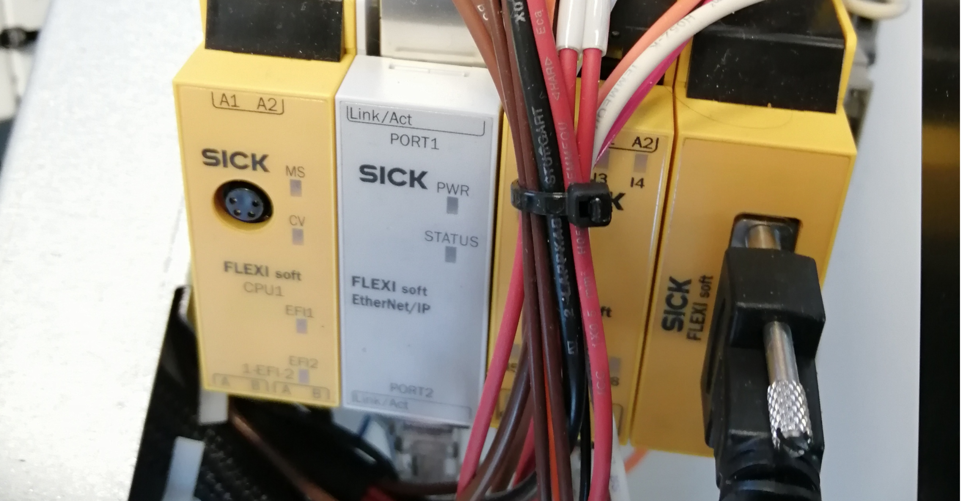
Composed by the following modules:
FX3-CPU130002
FX0-GENT00000
FX3-XTIO84002
FX3-MOC000000
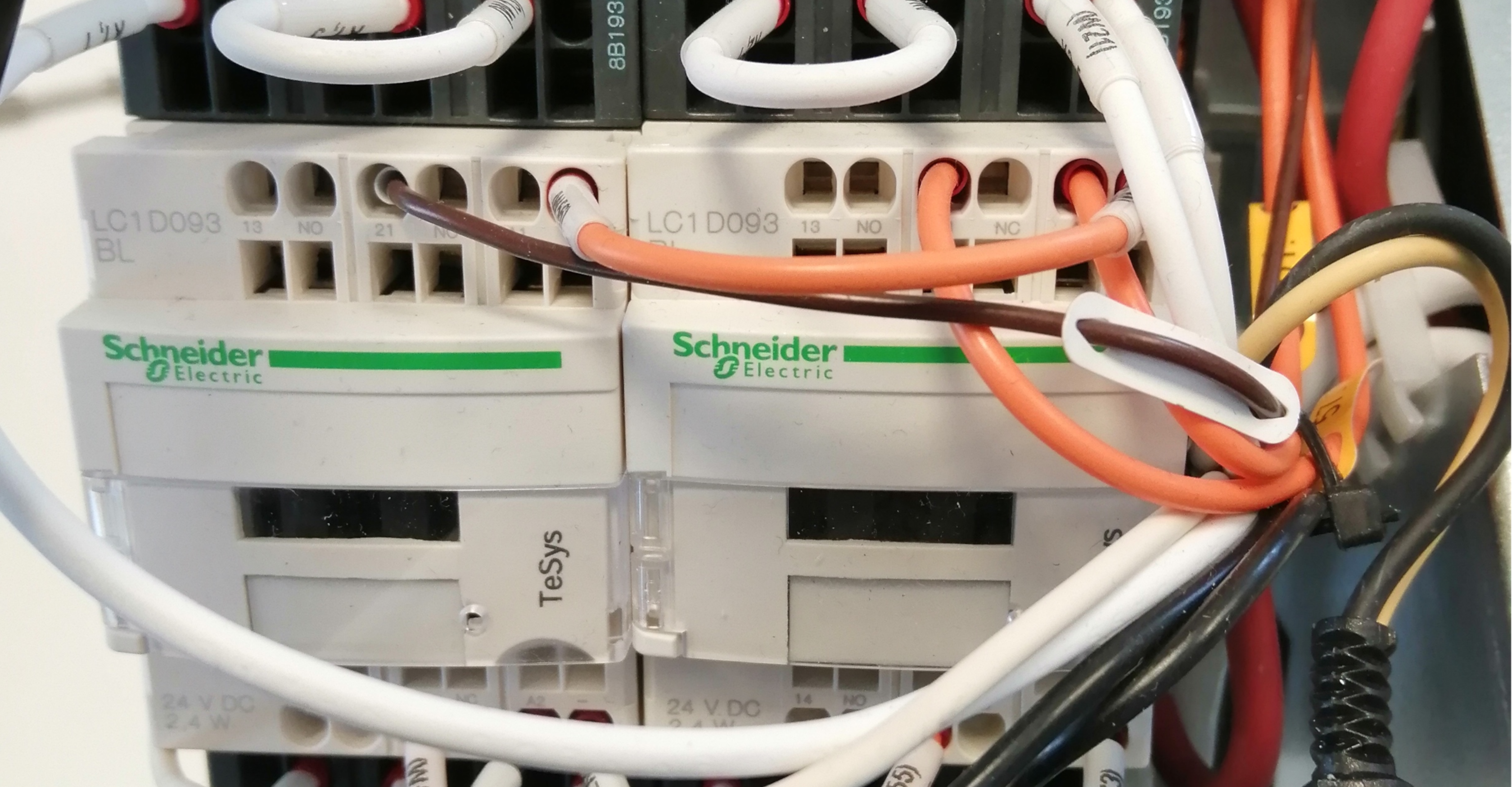
3-pole reversing contactors for motor control
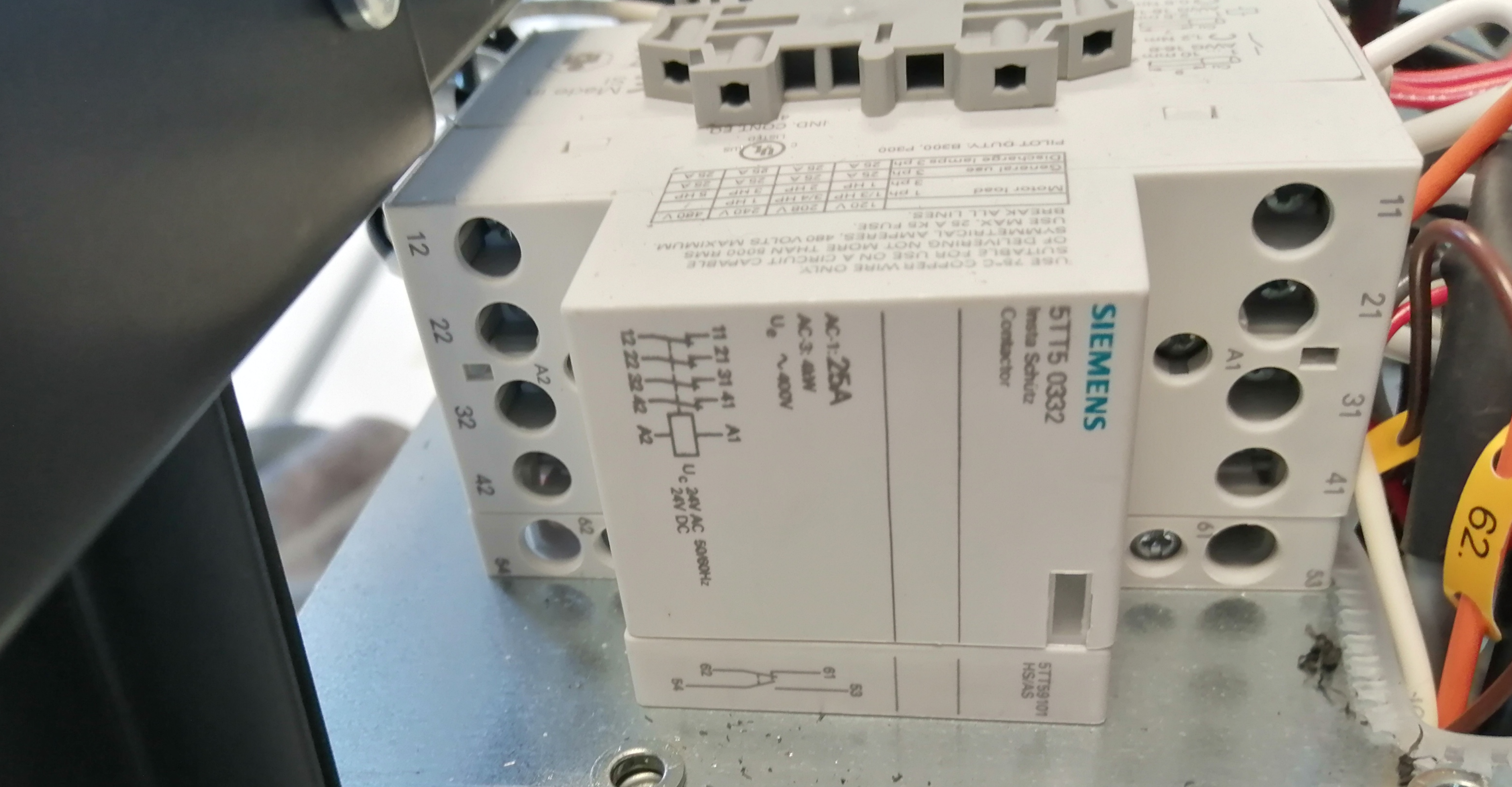
Contactor
Protection mechanism against voltage spikes induced on connected wires.
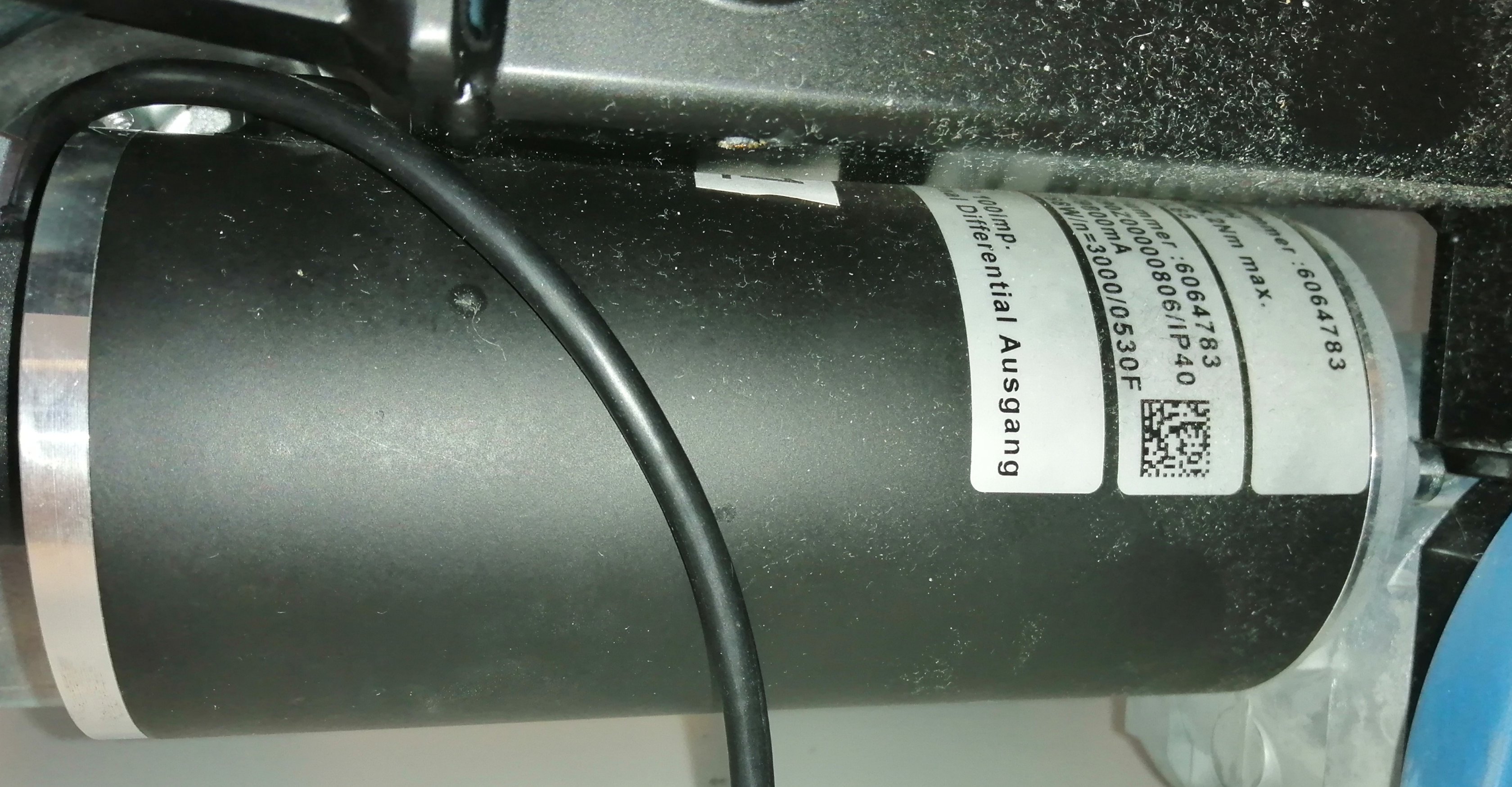
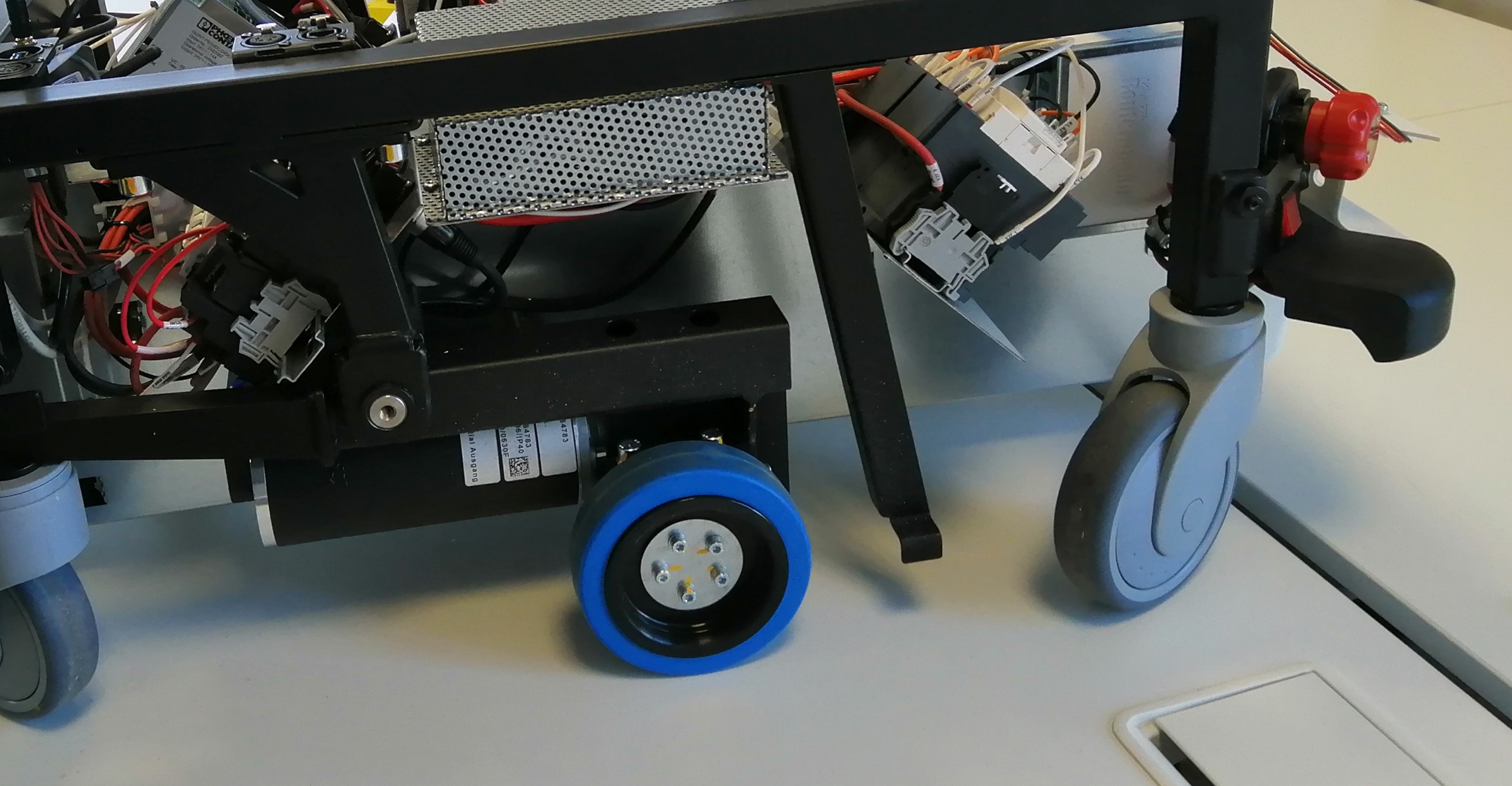
Made out of the following parts:
RV 30 incremental encoder
PN 8390 Motor
SC401H Single-stage worm gear
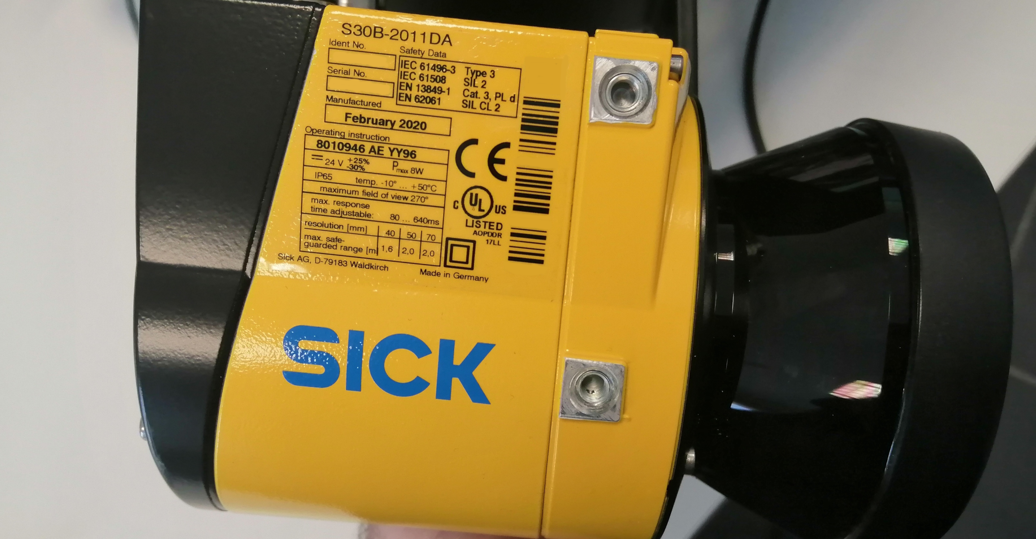
Safety laser scanner

At Alias Robotics we encourage a security-first approach to robotics. One that focuses on continuous monitoring and management of robot security risks and threats, leveraging modern tools and automation techniques to ensure that, at all times, the robots stay safe and secure.
We strongly believe that vulnerability disclosure is a two-way street where both vendors and researchers must act responsibly. Teardown, as a process, is an essential part of a security research and brings useful lessons and insights for the design of current and future robotic systems. Generally, teardown supports Kerckhoffs' principle in revealing all the details and weaknesses of a security system. Overall, the history of proprietary systems violating Kerckhoffs' principle by pursuing security through obscurity is rich of failure cases (with the military domain as the sole exception). We advocate against security by obscurity.
Alias remains committed to treating all vendors strictly equally and we expect to be held to the same standard.